Show the sample that gets analog input data (CH0 to CH3) every one second from our device and displays it on the graph.
This setting example assumes that the following components are placed in the form.
*Other than DncDaq is using default settings.
①Register AIO000 with device setting.
②Change DncDaq to Advanced mode.
③Perform sampling setting.
④Set 1 second cycle with timing setting.
⑤In the input task, link the data of the device to Graph at the timing set in ④.
⑥Perform task linkage by DncGraph.
⑦Build and execute in Visual Studio.
Display dncGraph on a Windows Forms application
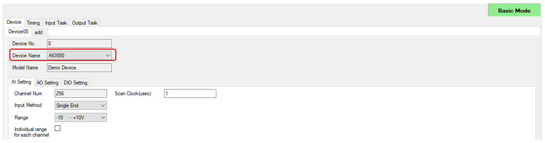
①Select [AIO000] in the device setting of DncDaq Property Screen.
In this example, "Demo Device" is selected.
The default settings are used, but you can set the input range and input method on the AI Setting tab.
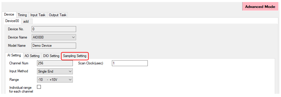
②Change DncDaq to Advanced Mode
・Click the Mode Label in the upper right of DncDaq, or the Mode Change button in the lower right of DncDaq to change to Advanced Mode.
・In Advanced mode, the [Sampling Setting] tab is added.
・For details, refer to the DncDaq Settings Panel.
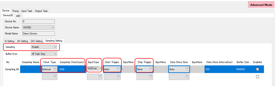
③Perform sampling setting
・Sampling Setting allow you to specify the hardware clock on the device or an external trigger signal on the device.
・Set the sampling function to [Disable] and perform the following sampling settings.
・Other settings use default settings.
Clock Type: Internal (Internal clock)
Sampling Clock(usec): 1000
InputType: VoltCurr (Voltage/Current value)
Start Trigger: Auto (Automatic perform at application startup)
Stop Trigger: None (Do not specify)
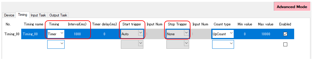
④In the timing setting, set the 1 second cycle.
・In the Timing, select Timer and specify 1000 msec with Interval(ms).
・In Advanced Mode, it is possible to specify the start trigger and stop trigger for timing. The timing selected in Timing occurs between start trigger and stop trigger.
・In this example, perform the following settings.
Start Trigger: Auto (Automatic perform at application startup)
Stop Trigger: None (Do not specify)
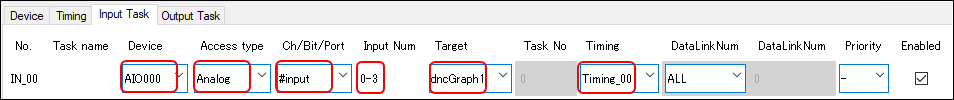
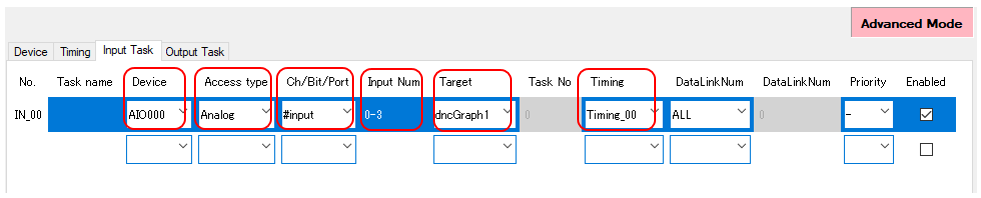
⑤In the input task, link the device data to Graph at the timing set in ④.
・Set the device name set in ① in the device.
・Specify Analog (voltage/current value) in the Access type and specify 0-3 in the Input Num.
・Select dncGraph1 added to the form at the Target, and select the Timing_00 set in ④ for Timing.
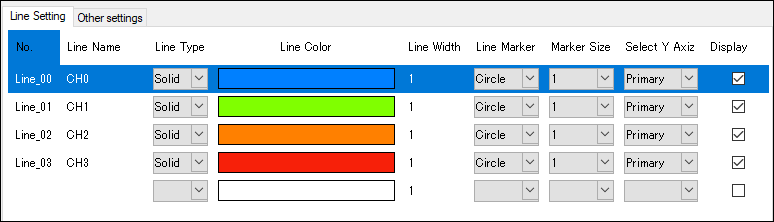
⑥Perform task linkage by DncGraph
・By opening the Property of the DncGraph component and performing the Use task setting, the input task settings set in ⑤ are reflected.
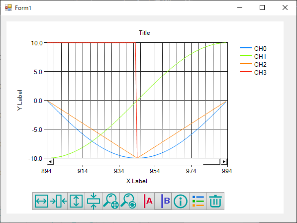
・If task linkage is successful, the line of 0-3ch is created if this example is created, and the Y axis of the graph is +/- 10V.
⑦Build and execute in Visual Studio.
Build and execute and make sure that the data is linked to the graph.
In this setting, the input data of 0CH to 3CH are linked, but setting change is possible in the following form.
・To link with binary value rather than voltage/current value ⇒ InputType for sampling settings: Please select Binary.
・To change sampling start/stop condition ⇒ Change the Start Trigger / Stop Trigger of sampling settings.
The above settings can be changed not only the screen display in the designer mode, but also the screen display in the application startup.
* For details, refer to the Show property screen.
DncDaq is set to perform automatic initialization at application startup by default.
If initialization is failed, the property page is displayed again. The factors that fail to initialize may be considered if you are trying to refer to a nonexistent device or not found the component registered in the task setting.
For details, refer to the [The
property screen is displayed when the application startup. (Init
fails.)]
|
 If DncDaq
Init processing (initialization processing) is failed
If DncDaq
Init processing (initialization processing) is failed