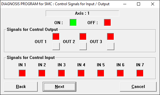
The [Control Signals
for Input / Output screen] has the following GUI (Graphical User
Inteface).
The screen displays the control output signal and control input signal
screens.
■ Control output signal
For the control output signal, the output
button and the status of the currently output signal are displayed. There
are two types of states.
The state in which the ON signal is output is indicated by ■
green, and the state in which the OFF signal is output is indicated by
■ red.
Each time you press the output button, the output status of each signal
changes.
■ Control input signal
For the control input signal, the status
of the currently input signal is displayed. There are two types of states.
The signal input (ON) state is indicated by ■
green, and the signal not input (OFF) state is indicated by ■
red.
If the expected control signal can be input/output,
click the [Next] button.
If the signal is not normal, check the wiring.
Click the [Cancel] button to return to the
Select Axis screen.
[Back]
Limit Signals for Input screen
[Next]
Pulse for Input / Output screen