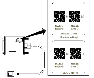

The host computer distinguishes and keeps track of the modules of same model by assigning Module IDs to them.
Factory settings [00] can be used when only one module per model is connected to one computer.
Each module should be assigned a unique Module ID in the range of 00 - 7Fh when several modules with the same model are being connected.
There are two rotary switches for setting the Module ID, "x16" and "x1" represent high bits and low bits of Module ID respectively.
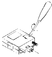
Use a flathead screwdriver to open the cover on the bottom of the product GPIB-FL2-USB, you will find the rotary switches for setting the Module ID.
As shown in the right figure, insert the tip of a flathead screwdriver into the groove and twist to open the cover.


There is no setup on the USB converter.
When using this product, please make sure that you are using the latest firmware.
For information on firmware updates, please click here.
After configuring the hardware device, please install the USB devices.
Initial setting of software are performed from the property page of Device Manager.
For more information, please refer to Initial Setting of Software.
※Please perform the initial setting of software after installing the hardware.