64bit environment: C:\Program Files (x86)\CONTEC\DAQ-LV-WIN\Samples
32bit environment: C:\Program Files\CONTEC\DAQ-LV-WIN\Samples
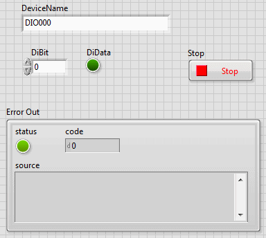
1. Open MonitorDi.vi from the DI folder of the sample VI folder

2. Enter the device name to be used in the [DeviceName] field and execute
the VI.
If the device name confirmed by the device manager is
[DIO000] (initial value), you can execute it as it is.
3. Change the input to bit 0 and check that the LED of DiData turns
on/off.
(If the input pin to be used is not bit 0, specify the
bit number to be used with DiBit)
If you can read the input change from the outside with DiData change,
the operation check is completed.
Please press [stop] button and close VI.
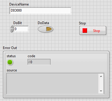
1. Open ControlDo.vi from the DO folder of the sample VI folder

2. Enter the device name to be used in the "DeviceName" field
and execute the VI.
If the device name confirmed by the device manager is
"DIO000" (initial value), you can execute it as it is.
3. Click on the DoData switch and check that the state of the digital
output to the outside changes.
(If the output pin to be used is not bit 0, specify the
bit number to be used with DoBit)
If you can check the output change to the outside, the operation check
is completed.
Please press [stop] button and close VI.
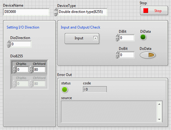
1. Open DioDual.vi from the DIO folder in the sample VI folder

2. Enter the device name to use in the [DeviceName] field.
If the device name confirmed by the device manager is
"DIO000" (initial value), you can leave it as it is.
3. Depending on the device to use, select "DeviceType".
- For the following products, please select
[double direction type]
DIO-24DY-USB
- For the following products, please select
[double direction type
(32DM)]
PIO-32DM(PCI),
DIO-32DM2-PE, DIO-32DM3-PE
For other double direction devices, you can
leave the initial value [double direction type (8255)] of this sample.
For [double direction type (8255)] device list,
please refer to [Device-specific
setting list] of VI reference.
4. Depending on the type of double direction device, set the input/output
direction with [DioDirection] or [Dio 8255].
In this example, set the input/output direction
to [input only] and check the operation.
- For the following products, [DioDirection]
can be left at the initial value [0].
DIO-24DY-USB
- For the following products, specify [0] or [1] for [DioDirection]
PIO-32DM(PCI),
DIO-32DM2-PE, DIO-32DM3-PE
For other interactive devices, specify [9B] for [Dio8255].
For details on direction setting, please refer
to [Channel setting VI
- ① Digital input/output (DIO)] of VI reference.
5. For [Input/output execution/confirmation], select [input only] (default value).
6. Run VI
7. Change the input to bit 0 and check that the LED of DiData turns
on/off.
(If the input pin to be used is not bit 0, specify the
bit number to be used with DiBit)
If you can read the input change from the outside with DiData change,
the operation check is completed.
Please press [Stop] button and close VI.