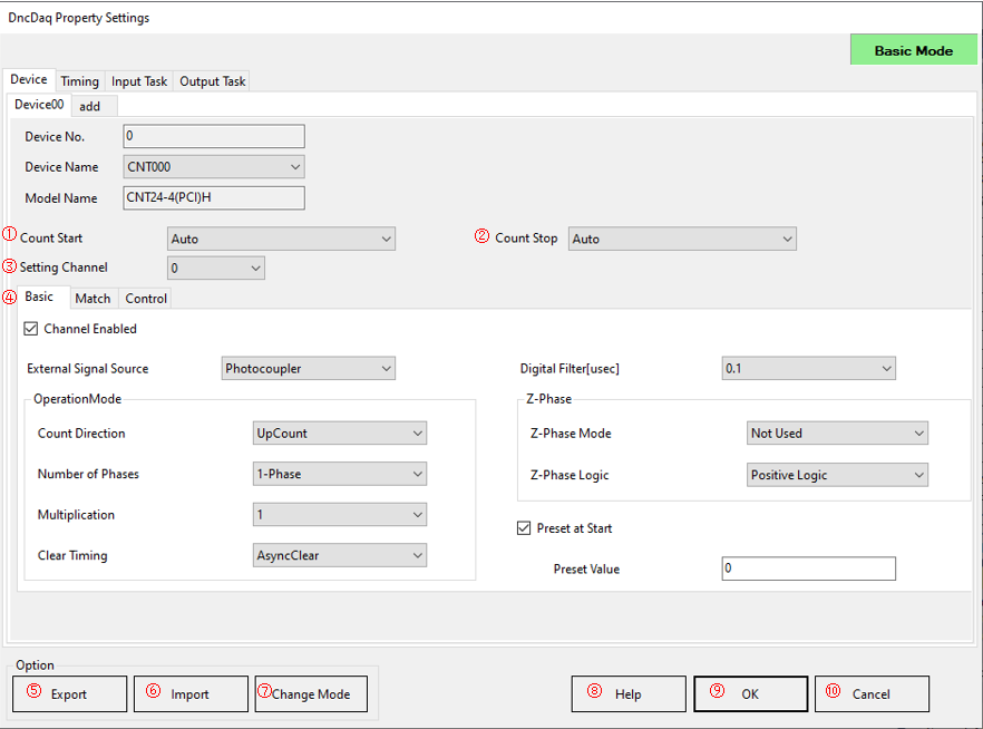
This section describes the CNT device setting screen.
On this screen, you can specify the setting channel and the method to start/stop
counting.

①Count Start
Select how to start counting operation.
・Auto: With DncDaq Init/Exit, a valid count channel will start.
・Button_Click: Start counting with a separately placed DncButton.
・Command: Start with the method.
②Count Stop
Select how to stop counting operation.
When the user application is terminated, counting will stop regardless of this setting.
・Auto: With DncDaq Init/Exit, a valid count channel will stop.
・Button_Click: Stop counting with a separately placed DncButton.
・Command: Stop with the method.
③Setting Channel
Count settings can be made for each channel.
If you want to set all channels with the same content at once, select [ALL].
④Counter setting tab
Three tabs for setting the counter device will be displayed.
There are three types of tabs:
・Basic tab: Set the basic functions related to count input.
・Match tab: Configure settings related to comparison matching.
・Control tab: Configure settings related to control input/output pins and general-purpose input/output.
⑤Export button
Displays a dialog to save the setting information being edited in the ini file format (xxx.ini).
⑥Import button
Displays a dialog to specify the ini file format (xxx.ini) to be read.
⑦Change Mode
Switch between Basic Mode/Advanced Mode.
⑧Help
Open the online help.
⑨OK button
Saves the settings and closes the settings screen.
⑩Cancel button
Closes the settings screen without saving the settings.

* It depends on your device to work the combination of counter operations properly. Please refer the hardware manual of your device.
①Channel Enabled
Enables the channel specified in Setting Channel.
②External Signal Source
Select the type of external signal source from the following.
・Photocoupler (Opto-coupler Isolation)
・TTL (Transistor Transistor Logic)
・Differential (Differential)
③OperationMode/Count Direction
Select the counting direction when a pulse is detected from the following.
・DownCount
・UpCount
④OperationMode/Number of Phases
Select the pulse to detect from the following.
・1-Phase
・2-Phase
・Gate Control
⑤OperationMode/Multiplication
Select the multiplication of pulses to detect from the following.
・Multiply by 1
・Multiply by 2
・Multiply by 4
⑥OperationMode/Clear Timing
Select the count value clear timing according to the Z phase from the following.
・Asynchronous Clear
・Synchronous Clear
⑦Digital Filter[usec]
Specify the digital filter value.
The settable range varies depending on the CNT Device Type of the device used.
・Normal counter: 0.1usec to 1,056.0usec
・High-performance counter: Not Used, 0.1usec to 1,638.4usec
⑧Z-Phase/Z-Phase Mode
Select the Z phase mode from the following.
・Not Used
・Next One Time
・Every Time
⑨Z-Phase/Z-Phase Logic
Select the Z phase logic from the following.
・Positive Logic
・Negative Logic
⑩Preset at Start
Specify whether to preset or not when counting starts.
⑪Preset Value
Set the preset value when presetting.
The available functions and setting screens vary depending on the CNT device type.
For information on CNT devices, please refer to FAQ [CNT device type].

①Register0/Notification Enabled
Specify enable/disable of register 0 comparison match notification.
②Register0/Comparative Value
Specifies the comparison value of register 0.
③Register0/Operation of Count Match Timing
Select the operation when the count value and the comparison value of register 0 match from the following.
Available only with high-performance counter devices.
・None: Does nothing.
・Preset: The separately set preset value is loaded to the count value.
・Clear: Clears the count value to zero.
④Register1/Notification Enabled
Specify enable/disable of register 1 comparison match notification.
Available only with high-performance counter devices.
⑤Register1/Comparative Value
Specifies the comparison value of register 1.
Available only with high-performance counter devices.
⑥Register1/Operation of Count Match Timing
Select the operation when the count value and the comparison value of register 1 match from the following.
Available only with high-performance counter devices.
・None: Does nothing.
・Preset: The separately set preset value is loaded to the count value.
・Clear: Clears the count value to zero.
⑦Preset Value
Set the count value to preset.
Available only with high-performance counter devices.
The preset values of register 0 and register 1 are common.
The available functions and setting screens vary depending on the CNT device type.
For information on CNT devices, please refer to FAQ [CNT Device Type].
<Normal counter device> 
①Pulse Width
Select the one-shot pulse width when the comparison value and count value match.
The setting range is 17 steps from 0msec to 104.45ms.
②Type of general input
Select the type of general-purpose input signal from the following.
Can be selected only for CNT24-4D(PCI)H.
・Differential (Differential)
・TTL (Transistor Transistor Logic)
<High-performance counter device>
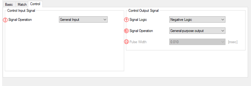
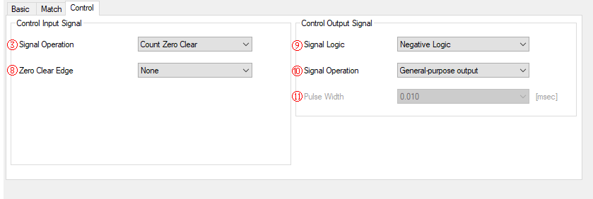
③Control Input Signal/Signal Operation
Select the operation to be performed when the control input signal is input from the following.
・General Input
・Count StartStop
・Count Preset
・Count Zero Clear
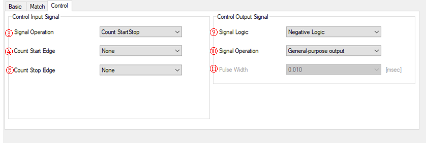
*When the [Signal Operation] is [Count StartStop], [Count Start Edge] and [Count Stop Edge] are displayed.
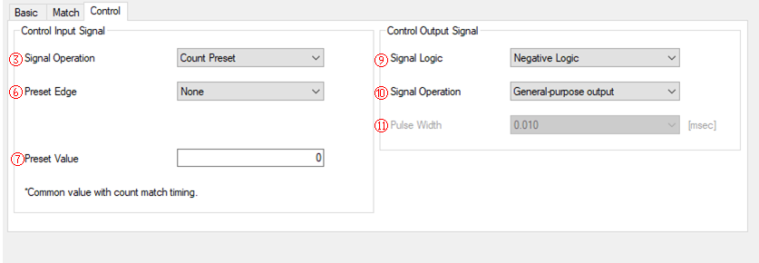
*When the [Signal Operation] is [Count Preset], [Preset Edge] and [Preset Value] are displayed.
*When the [Signal Operation] is [Count Zero Clear], [Zero Clear Edge] is displayed.
④Control Input Signal/Counting Start Edge
Select the edge of the control input signal to start counting from the following.
Displayed only when the [Signal Operation] is [Count StartStop]. It is not displayed at other times.
・None
・Rise
・Fall
⑤Control Input Signal/Counting Stop Edge
Select the edge of the control input signal to stop counting from the following.
Displayed only when the [Signal Operation] is [Count StartStop]. It is not displayed at other times.
・None
・Rise
・Fall
⑥Control Input Signal/Preset Edge
Select the edge of the control input signal to preset the count value from the following.
Displayed only when the [Signal Operation] is [Count Preset]. It is not displayed at other times.
・None
・Rise
・Fall
⑦Control Input Signal/Preset Value
Set preset value.
This is common to the preset value in the Match tab.
Displayed only when the [Signal Operation] is [Count Preset]. It is not displayed at other times.
⑧Control Input Signal/Zero Clear Edge
Select the edge of the control input signal to clear the count value to zero from the following.
Displayed only when the [Signal Operation] is [Count Zero Clear]. It is not displayed at other times.
・None
・Rise
・Fall
⑨Control Output Signal/Signal Logic
Select the control output signal logic from the following.
・Negative Logic
・Positive Logic
*Not displayed for CNT32-8M(PCI) and CNT-3208M-PE. Please specify with the jumper on the device.
⑩Control Output Signal/Signal Operation
Select the timing at which the control output signal is output from the following.
・General-purpose output
・Count Match Register0
・Count Match Register1
・Filter Erroe
・Abnormal Input Error
・Disconnection Alarm Error
⑪Control Output Signal/Pulse Width
Select the one-shot pulse width of the control output signal from the following.
・0.010msec (10usec)
・0.100msec (100usec)
・1msec
・10msec
・100msec