
-Contents
-Use function
Initialization function( SmcWSetPulseType SmcWSetEncType )
-Outline
It initializes it by using the initialization function.
-Operation method
The set axis is selected with the device name and AxisNo (axis number).
PulseOut(setting of output pulse)
PulseType(The pulse output mode is set. )SmcWSetPulseType function
The PulseType is displayed by the sort order of parameter: PulseMode.
Common pulse method OUT: Negative logic, DIR+: High, DIR-: Low
Common pulse method OUT: Positive logic, DIR+: High, DIR-: Low
Common pulse method OUT: Negative logic, DIR+: Low, DIR-: High
Common pulse method OUT: Positive logic, DIR+: Low, DIR-: High
2-pulse mode: Negative logic
2-pulse mode: Positive logic
Phase difference mode of 90 degrees OUT:Leading,DIR:Trailing
Phase difference mode of 90 degrees OUT:Trailing,DIR:Leading
Reverse Direction Timer ON
The weight (delay) at 200 microseconds is inserted before the pulse is output when the direction changes by the change in the DIR change when the common pulse method is set.(It is effective only for the common pulse method. )
S Accel/Decel Use
PulseIn(Setting of encoder input pulse)
Encoder Type(encoder type) SmcWSetEncType function
A/B two-phase input 1 times
A/B two-phase input 2 times
A/B two-phase input 4 times
U/D single-phase input 1 times
The return value is displayed in the comment, and execute it again, please after confirming the content of the error and the correspondence when the setting is not effective.
Please push [Set] when you reflect the setting in the device.
Please push [Status] when you check the completion of initialization .
Please push [EXIT] when you end this program.
-Use function
Initialization function( SmcWSetCtrlTypeOut SmcWSetCtrlTypeIn SmcWSetInFilterType SmcWSetSDMode )
-Outline
The I/O of the output three points and the input seven points is set.
-Operation method
OUT Setting SmcWSetCtrlTypeOut function
General-Purpose output
Alarm Clear
Counter Clear (ERC)
OutPulse Count Match(CP1)
Encoder Count Match(CP2)
Hold OFF
IN Setting SmcWSetCtrlTypeIn function
General-Purpose input
ALM(Alarm)
INP(Servo driver's positioning completion signal input)
SD(Slow down)
LTC signal(The latch does COUNTER1-2.)
PCS signal(The positioning operation of this signal input begins.)
CLR(Counter clear)
In Filter(LIM, SD, ORG, ALM, INP, The input filter is set.)
SmcWSetInFilterType function
none
3.2[usec]
25[usec]
200[usec]
1.6[msec]
SD Mode(Slow down mode) SmcWSetSDMode function
Deceleration stop
Only the deceleration(to beginning speed)
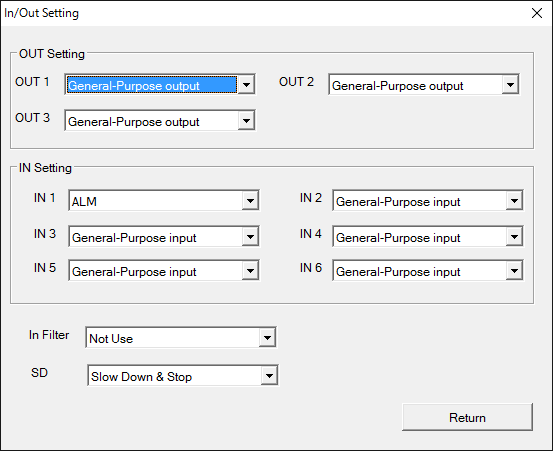
Please push [Return] when the setting is completed. It returns to the Setting screen.
-Use function
Initialization function( SmcWSetCtrlInOutLog )
-Outline
The logic of the I/O signal (positive logic/negative-true logic) is set by using the initialization function.
-Operation method
OutLogic SmcWSetCtrlInOutLog function
High Active(positive logic)
Low Active(negative-true logic)
In Logic SmcWSetCtrlInOutLog function
High Active(positive logic)
Low Active(negative-true logic)
Limit Logic SmcWSetCtrlInOutLog function
High Active(positive logic)
Low Active(negative-true logic)

Please push [Return] when the setting is completed. It returns to the Setting screen.
-Use function
Initialization function( SmcWSetOrgMode SmcWSetOrgLog )
-Outline
The starting point resume operation is set by using the initialization function.
-Operation method
ORG Type SmcWSetOrgMode function
Z USE
Z Count(Range 1-16 of setting)
EndDirType(The direction where it is rushed into that the starting point returns the starting point is set. )
Disable(doesn't specify it)
Plus Dir(Positive direction)
Minus Dir(Negative direction)
ORG Logic
SmcWSetOrgLog function
Positive logic/negative-true logic of the ORG signal is set.
Positive logic/Rising edge-Falling edge logic of Z signal is set.
LimitTurn Use SmcWSetOrgMode function
The limit doesn't reverse.
The limit reverses.
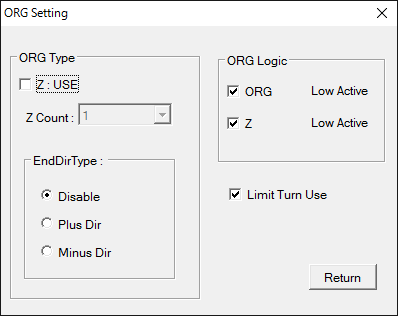
Please push [Return] when the setting is completed. It returns to the Setting screen.
-Use function
Initialization function ( SmcWSetErcAlmClearTime SmcWSetErcMode )
-Outline
The width etc. of a clear signal are set by using the initialization function.
-Operation method
Counter Clear(ERC)
Stop by LIM and ALM input
0 : When stopping by LIM and the ALM signal input, the ERC signal is not output.
1 : When stopping by LIM and the ALM signal input, the ERC signal is output.
ORG motion end
0 : When the starting point resume operation is completed, the ERC signal is not output.
1 : When the starting point resume operation is completed, the ERC signal is output.
Counter Clear Time(The width of a deflection counter clear signal is set. )
12[usec]
102[usec]
408[usec]
1.6[msec]
13[msec]
52[msec]
104[msec]
Level output
Counter Off Timer(The time of deflection counter clear signal OFF timer is set. )
0[usec]
12[usec]
1.6[msec]
104[msec]
Alarm Clear Time(The width of an alarm clear signal is set. )
12[usec]
102[usec]
408[usec]
1.6[msec]
13[msec]
52[msec]
104[msec]
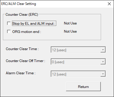
Please push [Return] when the setting is completed. It returns to the Setting screen.
-Use function
-Outline
A clear latch is set by using the initialization function.
-Operation method
LTC
-Clear Counter
No Clear
Out Pulse
Encoder Pulse
Out & Encoder Pulse
-Latch Counter
No Use
Out Pulse
Encoder Pulse
Out & Encoder Pulse
CLR
-Clera Counter
No CLear
Out Pulse
Encoder Pulse
Out & Encoder Pulse
-Mode
No Use
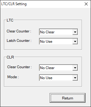
Please push [Return] when the setting is completed. It returns to the Setting screen.