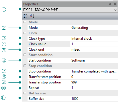
Property window
Condition is set by selecting the property window.
Set the items that need to be changed in order from the above properties.
Property window
A list of devices that can be used with this software will be displayed in the list, so select the device you want to use.
Select Generating/Sampling.
Settings |
Description |
Internal clock |
Perform Generating at the timing of the internal clock. In this case, set the following clock values. |
External clock |
Perform Generating at the timing of the external clock. |
Handshake |
Perform generating using handshake with external equipment. |
This setting takes effect when you select the internal clock as the
clock.
Specify the internal clock value in the unit specified in "Clock unit".
Device name |
Settable range |
DIO-32DM3-PE |
20nsec≦ Clock value ≦ 21sec(5nsec unit) |
PIO-32DM(PCI) |
50nsec≦ Clock value ≦ 107sec(25nsec unit) |
* If the number of transferred data exceeds
the size of the FIFO of the device,
it depends on the PC, but the actual settable range is
about 100ns or more.
Settings |
Description |
1s |
Set the internal clock in seconds. |
1ms |
Set the internal clock in milliseconds. |
1μs |
Set the internal clock in microseconds. |
1ns |
Set the internal clock in nanoseconds. |
Select the conditions to stop data transfer.
Settings |
Description |
Software |
Data transfer starts unconditionally when the Start Device Operation button is pressed. |
Rising edge of external trigger |
After the Start Device Operation button is pressed, data transfer starts at the rising edge of the external start signal. |
Falling edge of external trigger |
After the Start Device Operation button is pressed, data transfer starts at the falling edge of the external start signal. |
Select the conditions to stop data transfer.
Settings |
Description |
Software |
When the stop button is pressed, the device operation ends. |
Rising edge of external trigger |
Data transfer is stopped at the rising edge of the external stop signal. |
Falling edge of external trigger |
Data transfer is stopped at the falling edge of the external stop signal. |
Transfer completed with specified number |
Transfers data for the specified number of clocks. |
Specify the position of the buffer to start the transfer.
Device name |
Recognized Memory |
OS |
Available range |
DIO-32DM3-PE |
- |
All supported OS |
0≦ Transfer start position ≦ 536,870,911 *2 |
PIO-32DM(PCI) |
The memory less than 4G Byte |
All supported OS *1 |
0≦ Transfer start position ≦ 16,515,071 *2 |
The memory more than 4G Byte |
Windows10 |
0≦ Transfer start position ≦ 262,143 *2 |
|
Windows10 |
0≦ Transfer start position ≦ 524,287 *2 |
Specify the position of the buffer to end the transfer.
Must be set after the transfer start position.
Device name |
Recognized Memory |
OS |
Available range |
DIO-32DM3-PE |
- |
All supported OS |
1≦ Transfer stop position ≦ 536,870,912 *2 |
PIO-32DM(PCI) |
The memory less than 4G Byte |
All supported OS *1 |
1≦ Transfer stop position ≦ 16,515,072 *2 |
The memory more than 4G Byte |
Windows10 |
1≦ Transfer stop position ≦ 262,144 *2 |
|
Windows10 |
1≦ Transfer stop position ≦ 524,288 *2 |
The data in the range specified by "Transfer start position"
and "Transfer end position" is output repeatedly for the specified
number of times.
To enable this setting, you need to select "Transfer completed with
specified number" as the stop condition.
Device name |
Available range |
DIO-32DM3-PE |
1≦ Repeat times ≦ (536,870,912(20000000H) ÷ ([Transfer stop position] - [Transfer start position] + 1)) |
PIO-32DM(PCI) |
1≦ Repeat times ≦ (16,777,215(FFFFFFH) ÷ ([Transfer stop position] - [Transfer start position] + 1)) |
Specify the size of the buffer for transfer. You can edit the data for the size set here.
Device name |
Recognized Memory |
OS |
Available range |
DIO-32DM3-PE |
- |
All supported OS |
1≦ Buffer size ≦ 536,870,912 *2*3 |
PIO-32DM(PCI) |
The memory less than 4G Byte |
All supported OS *1 |
1≦ Buffer size ≦ 16,515,072 *2 |
The memory more than 4G Byte |
Windows10 |
1≦ Buffer size ≦ 262,144 *2 |
|
Windows10 |
1≦ Buffer size ≦ 524,288 *2 |
*1 : If the [Memory Reclaiming] function is enabled in the BIOS settings
of the PC (motherboard) on which the board is mounted, the settable range
will be the same as when recognizing memory of 4 GByte or more.
*2 : Depending on how the buffer area is mapped to the physical address
space, it may not be possible to set the maximum value.
*3 : For DIO-32DM3-PE, if the buffer size is set to less than 2048, the
transfer rate will decrease due to hardware restrictions.