In the case of CSV form, the information of settings and conditions (at which the acquisition is performed), is saved to the file before the acquired data is saved.
The following
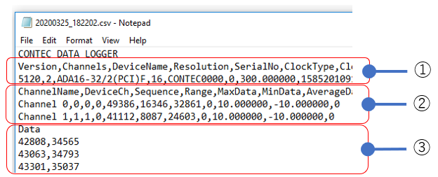
figure shows the image that the file saved as CSV form is opened in Notepad.
The first line contains the "CONTE
DATA LOGGER" character.
The second and subsequent lines consist of three blocks.
Blocks in collection data files |
Description |
①Acquisition execution information |
Saves the conditions and information on the acquisition. |
②Acquisition channel information |
Saves channel information when acquisition was performed. |
③Acquired data |
Saves acquired data for each channel. Data to be saved are binary values. |
It consists of 2 lines.
16 items on 1 line, separated by commas (","). (See table below)
Line 1 is the "item names," separated
by commas (",").
Line 2 is the values, separated by commas (",").
No. |
Item |
Value (Example) |
Description |
1 |
Version |
5120 |
Version information of C-LOGGER by which the file is created. (*1) |
2 |
Channels |
2 |
Total number of channels used in acquisition. |
3 |
DeviceName |
ADA16-32/2(PCI)F |
DeviceName used in acquisition. |
4 |
Resolution |
16 |
Resolution (in number of bits) of device used in acquisition. |
5 |
SerialNo |
CONTEC0000 |
Serial number used in acquisition. (*1) |
6 |
ClockType |
0 |
Clock type with the following numbers. 0: Internal Clock |
7 |
Clock |
10.000000 |
Sampling Clock Period used in acquisition. |
8 |
Time Integer |
1583394745000000 |
Integer value converted from the time and date at which acquisition is started. (*1) |
9 |
SamplingStartDate |
2020/03/05 13:19:05'000"000 |
Time and date at which acquisition is started. |
10 |
Stop Time Integer |
1583394746000000 |
Integer value converted from the time and date at which acquisition is stopped. (*1) |
11 |
SamplingStopDate |
2020/03/05 13:19:06'000"000 |
Time and date at which acquisition is stopped. |
12 |
Number |
1000 |
Number of acquired data per channel. |
13 |
RepeatNum |
1 |
Saves the acquired repeat times settings. |
14 |
DelayNum |
0 |
Saves the acquired conversion stop delay sampling times settings. |
15 |
StopTriggerPoint |
1000 |
Saves the number of data when the stop trigger is activated. |
16 |
NumberOffset |
0 |
For the second and subsequent split saves, saves the number of samplings saved separately. (*1) |
*1: Internal information used by C-LOGGER. The value may change depending on the version of C-LOGGER.
The number of rows consists of the value
of "Channels" +1.
For example, when Channels = 2, there are 3 rows.
Up to 15 items are separated by commas (",")
on 1 row.
The number of items varies depending on the ScalingEnable setting.
ScalingEnable = 0 (no scaling) results in 11 items.
ScalingEnable = 1 (scaling) results in 15 items.
Line 1 contains item names separated by commas
(",").
Lines 2 and beyond contain values separated by commas (",").
No. |
Item |
Value (Example) |
Description |
||||||||||||||||||||||||
1 |
ChannelName |
Channel 0 |
ChannelName of acquired channel. |
||||||||||||||||||||||||
2 |
DeviceCh |
0 |
Channel Number of Device. |
||||||||||||||||||||||||
3 |
Sequence |
0 |
Channel conversion sequence used in acquisition. |
||||||||||||||||||||||||
4 |
Range |
0 |
Input range specified to device used in acquisition is saved as numerical value. Please refer to the following table for the input range to the numerical value.
|
||||||||||||||||||||||||
5 |
MaxData |
4095 |
Maximum value of the acquired data. The data to be saved is a binary value. |
||||||||||||||||||||||||
6 |
MinData |
0 |
Minimum value of the acquired data. The data to be saved is a binary value. |
||||||||||||||||||||||||
7 |
AverageData |
2047 |
Average value of the acquired data. The data to be saved is a binary value. |
||||||||||||||||||||||||
8 |
ScalingEnabled |
0 |
Whether scale conversion is used in acquisition is saved as numerical value. 0: Scale conversion is not performed |
||||||||||||||||||||||||
9 |
RawDataA |
(Omitted) |
Voltage value corresponded to ScaleDataA. It may be omitted when ScalingEnabled = 0. |
||||||||||||||||||||||||
10 |
RawDataB |
(Omitted) |
Voltage value corresponded to ScaleDataB. It may be omitted when ScalingEnabled = 0. |
||||||||||||||||||||||||
11 |
ScaleDataA |
(Omitted) |
Converted voltage value corresponded to RawDataA. It may be omitted when ScalingEnabled = 0. |
||||||||||||||||||||||||
12 |
ScaleDataB |
(Omitted) |
Converted voltage value corresponded to RawDataB. It may be omitted when ScalingEnabled = 0. |
||||||||||||||||||||||||
13 |
MaxScale |
10.000000 |
Maximum value of input data. When scale conversion is used, it is the converted value. |
||||||||||||||||||||||||
14 |
MinScale |
-10.000000 |
Minimum value of input data. When scale conversion is used, it is the converted value. |
||||||||||||||||||||||||
15 |
Option |
0 |
Option information. (*1) |
*1: Internal information used by C-LOGGER. The value may change depending on the version of C-LOGGER.
The number of rows consists of the value
of "Number" +1.
For example, Number = 1000 consists of 1001 rows.
Line 1 contains the character "Data".
Line 2 contains the values of each channel, separated by a comma (",").
The following rows contain the values in chronological order.
Each channel value is stored as a binary
value (10 decimal).
The binary value is the actual data value input from the device, before
it is converted to a voltage value.
If you want to convert to a voltage value or current value, refer to "Convert Binary value to Voltage value" topic.