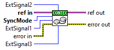

Select when setting synchronous operation on a analog device

SyncMode |
Initial value: 0 (StandAlone) |
[Essential]
Select synchronous mode
0:
StandAlone
1: Master
2: Slave
- Stand-alone
Specify this when using the device alone or without using it in sync with
other devices
- Master
Specify this when performing synchronous operation with the target board
as the master
- Slave
Specify this when performing synchronous operation with the target board
as a slave
ExtSignal1 |
Initial value: 0 |
ExtSignal2 |
Initial value: 0 |
ExtSignal3 |
Initial value: 0 |
When using with master or slave, set synchronization
control signal
No need to specify for Stand-alone
- In case of master
Specify the signal to be output to the three terminals (ExtSignals 1 to 3) of the synchronous control connector
Value |
Output signal |
0 |
Not Used |
Analog input signal |
|
1 |
Software start (AI/AO common) |
2 |
Software stop (AI/AO common) |
3 |
AI internal clock |
4 |
AI level trigger start |
5 |
AI level trigger stop |
6 |
AI conversion times stop(Not delay) |
7 |
AI conversion times stop(Delay) |
Analog output signal |
|
101 |
Software start (AI/AO common) |
102 |
Software stop (AI/AO common) |
103 |
AO internal clock |
104 |
AO specified times output stop(FIFO) |
105 |
AO specified times output stop(RING) |
Which signal is assigned to each of the three terminals of the synchronous control connector is arbitrary by the user, but we recommend the following assignment as standard and recommended. Synchronous
Control Signal 1 (ExtSignal1): Clock signal
|
- In case of slave
Specify whether to use each Synchronous Control Signal (ExtSignal 1 to 3)
Value |
Use or not |
0 |
Invalid |
1 |
Valid |