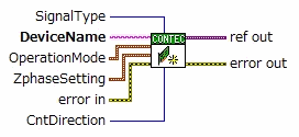

For counter device with sampling function, select it for counter input and sampling.

DeviceName |
Initial value: "CNT000" |
[Essential]
Specify the name (device name) of the device
to be used
You can set and check the device name in Device Manager
OperationMode |
"-1" can be set |
Initial value: 1:0:0 |
Specify the operation mode (Number of phases, Clear, Multiplier) with a three-element cluster
■ Element 1: Phase
Specify the number of phases of the pulse to be input
0:
1-phase
1: 2-phase
2: Gate control
■ Element 2: Multiplier
Specify multiplier of the pulse to be input
0:
1x
1: 2x
2: 4x
■ Element 3: SyncClear
Specify clear condition (Synchronous clear/Asynchronous clear)
0: Asynchronous
clear
1: Synchronous clear
* Initial setting is "2-phase", "1x", "Asynchronous clear"
ZphaseSetting |
"-1" can be set |
Initial value 0:1 |
Specify the usage of Z-phase and logical setting in a two-element cluster
■ Element 1: Usage(ZMode)
Specify how to use Z-phase
0:
Not Used
1: Next One Time
2: Every Time
■ Element 2: Logic (ZLogic)
Specify Z-phase input logic
0:
Positive logic
1: Negative logic
* Initial setting is "Not Used", "Negative logic"
SignalType |
"-1" can be set |
Initial value 1 (TTL) |
Specify the signal type (Photocoupler/TTL/Differential) of the pulse to be input
0:
Photocoupler
1: TTL
2: Differential
* For the signal types that can be set, refer to the explanation manual of the used device
CntDirection |
"-1" can be set |
Initial value: 1 (up count) |
Specify count direction
0:
Down count
1: Up count
There
is an initial value for each input terminal setting. setting "CntDirection" does not need to be set especially when using it in up-counting.
|