
This section describes the input task setting screen in Advanced mode.
On this screen, in addition to the contents of Basic mode, you can set the number of data linkages and task priority in continuous mode.
①#Input
Indicates the task No.. You can create up to 100 types of task settings (0 to 99).
②Task name
You can set the task name.
③Device
You can select the device name registered in the device settings.
④Access type
Select how to get the data from the device. The items that can be selected differ depending on the device.
Also, for devices with sampling settings enabled, only the acquisition method (voltage/current or binary value) set in the sampling settings is displayed.
Item |
Target device |
Description |
Analog |
AIO device |
Specifies the analog input (voltage/current value) for each channel. |
AnalogBinary |
AIO device |
Specifies the analog input (binary value) for each channel. |
Count |
CNT device |
Specifies the counter value for each channel. |
DigitalBit |
AIO device/DIO device |
Specifies the digital input in bits. |
DigitalPort |
AIO device/DIO device |
Specifies the digital input in ports(8-bit unit). |
DigitalOutBit |
DIO device |
Specifies the digital output state in bits. |
DigitalOutPort |
DIO device |
Specifies the digital output state in ports(8-bit unit). |
⑤InCh/Bit/Port
Select the method for specifying the linkage unit specified in ④.
Item |
Description |
#input |
Enter using the input field on the right. |
DncTextBox |
Use the Text property of the DncTextBox that exists on the form. Please use it when the user wants to change the acquired data while the application is running. The Text property of DncTextBox is referenced when DncDaq Init
method is performed. |
At the time of input, it is possible to input numerical values such as "0" and "1", specify them separated by commas such as "0,1,3", and specify sequential numbers with hyphens such as "0-3".
For the contents that are permitted or prohibited, please refer to Input rule when specifying channel/bit/port.
Specifies the link destination of the input data. The link destination can be selected from the following.
Item |
Description |
Button |
Data is linked to the Button control. (Selectable only for DigitalBit/Port and DigitalOutBit/Port) |
DataSet |
Data is linked to the DataSet control. |
FFT *1 |
Data is linked to FFT control. (Selectable only for Analog) |
Graph |
Data is linked to the Graph control (selectable only for Analog and AnalogBinary) |
Label |
Data is linked to the Label control. |
Lamp |
Data is linked to the Lamp control. (Selectable only for DigitalBit/Port and DigitalOutBit/Port) |
Level *2 |
Data is linked to the Level control. (Selectable only for Analog, AnalogBinary, and Count) |
Meter *2 |
Data is linked to the Meter control. (Selectable only for Analog, AnalogBinary, and Count) |
TaskValue |
Stores
the value in Value of the task. |
TextBox |
Data is linked to the TextBox control. |
WriteFile |
Data is linked to the WriteFile control. |
#OUT-TaskValue |
Stores
the value in TaskValue of Output task. |
*1 If the sampling function of the AIO device is enabled, DaLinkNum cannot select All. Please select a power of 2 for the number of data linkages.
*2 When selecting Analog or AnalogBinary, it cannot be selected if the sampling function of the AIO device is enabled.
⑦Task No
This is enabled when "#OUT-TaskValue" is selected at ⑥ Target.
Please specify the output task No. to store the input data.
*An error will occur if the input data and the data type specified in the output task are different.
Specifies when to input the data. In addition to the following items, you can select the contents set in the Timing setting.
Item |
Description |
Init |
When the automatic initialization of InitMode is enabled, it is input when the application is started, and when it is disabled, it is input when Init is executed. |
Exit |
Performs input when exiting the application or executing the Exit method. |
Timing_XX |
Select the content set in the Timing setting. No. is entered in the XX part. (00-99) |
⑨DataLinkNum
This is valid only when "Analog" or "Analog Binary" is selected on a device for which sampling settings are enabled.
Set the number of data stored in the task to be linked.
If ALL is selected, all the data in the buffer will be linked.
If the number of data in the task buffer is less than the specified number when the number of data is specified, the data linkage will not be performed and the task buffer will be checked again at the next timing.
Cannot be selected for DIO and CNT devices.
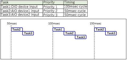
⑩Priority
When executing tasks at the same timing, specify the priority of each task number as 1-9.
If "-" is selected or the same priority is specified, it will not be specified.
Please refer to the following for the execution image.
⑪Enabled
You can select whether to enable/disable the input settings.