This section describes the AIO device setting screen in Basic mode.
On this screen, analog input settings, analog output settings, and digital filter settings are possible.
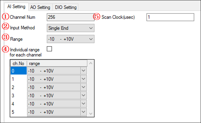
The input method, input range, and scan clock can be set.

①Channel Num
Shows the number of channels available on the selected device.
②Scan Clock(usec)
Sets the scan clock.
This cannot be set if a device that does not support the scan clock setting
is selected.
③Input Method
Select the input method.
Single End input and Differential input can be selected.
The input method supported by the device is displayed in the list.
④Range all
Sets the input range for all channels.
The input ranges supported by the device is displayed in the list.
⑤Range
If you want to set the range for each channel individually, you can set it individually from the list at the bottom by enabling this check box.
It cannot be enabled if the device does not support individual range settings.
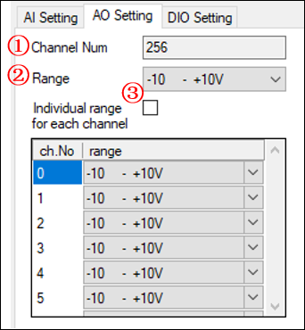
The output range can be set.

①Channel Num
Shows the number of channels available on the selected device.
②Range all
Sets the output range for all channels.
The output ranges supported by the device is displayed in the list.
③Range
If you want to set the range for each channel individually, you can set it individually from the list at the bottom by enabling this check box.
It cannot be enabled if the device does not support individual range settings.
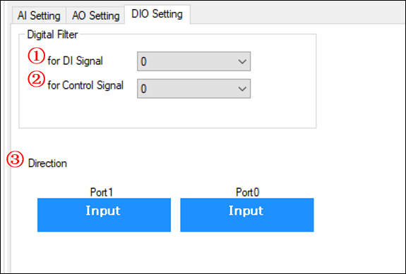
Digital filter setting and input/output direction setting are possible.

①DI Signal Digital filter setting
Sets the digital filter (usec unit) for the digital input signal.
If the filter time cannot be set, an error message will be displayed.
For the digital filter values that can be set, please see the digital filter setting list.
②Control Signal Digital filter setting
Sets the digital filter (usec unit) for the external control signal (external clock signal, external start/stop signal).
If the filter time cannot be set, an error message will be displayed.
For the digital filter values that can be set, please see the digital filter setting list.
③Input/output direction setting
Switches the input/output direction of the digital signal.
By clicking the displayed Input/Output, the input/output direction will change.
This screen will not be displayed for unsupported devices.