Follow the steps below to connect to the
IO-LINK master unit with ModbusTCP.
For the hardware details, please refer to
the product manual.
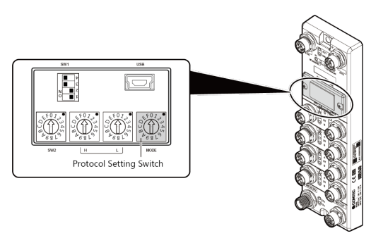
To use Modbus protocol, set the protocol
setting switch of the IO-LINK master unit to "2".
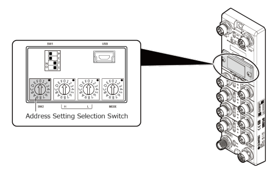
To set IP address of the IO-LINK
master unit, set the "Address setting method selection switch"
to "2: Fixed address".
The default IP address is "192.168.1.102". The IP address
can be changed from the Web setting screen or from the switch on the
main unit.
Please refer to the product manual for details.
Connect the host PC on which this
sample collection is installed and the IO-LINK master unit with a
LAN cable and turn on the power.
For the network settings (IP address) on host PC, please refer to the
product manual.
■ Modbus Communication Example
The IO-LINK master unit can acquire the acquired
sensor information by Modbus protocol.
The following is an example of acquiring
process data when the OMRON proximity sensor "E2E-X7B4-M1Tj-IL3"
is connected to IO-Link port 1 and channel 1 of CPSL-08P1EN.
Please refer to the product manual for detailed
address maps and functions.
Modbus connection
Specify IP address and port with modbus_new_tcp
function, and connect to the IO-LINK master unit with modbus_connect
function.
* Normally, Modbus TCP/IP uses 502 (TCP port).
IO-LINK mode switching
The IO-LINK mode of the IO-LINK master unit has a mode corresponding
to the connected target.
In general, when connecting a IO-LINK compatible sensor, it is necessary
to switch the connected port to "IO-LINK" mode.
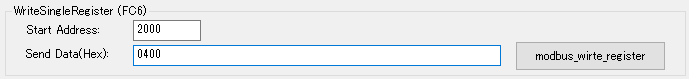
To switch to IO-LINK mode, write 0x0400 to the Modbus register:2000
(Port Mode) by using Write Single Register (FC6) etc.
- Writing example which used a sample
Functions used : modbus_write_register
function
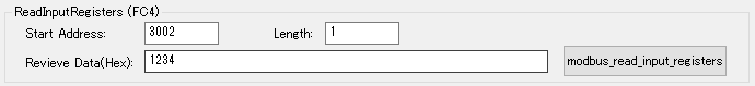
Sensor data collection
The data of the sensor connected to IO-LINK port 1 and channel 1 is
mapped to the Modbus register: 3002.
Data can be obtained using Read Input Registers (FC4) etc.