The control I/O signal is confirmed by using the control signal setting function.
Please push [EXIT] when you end this program.
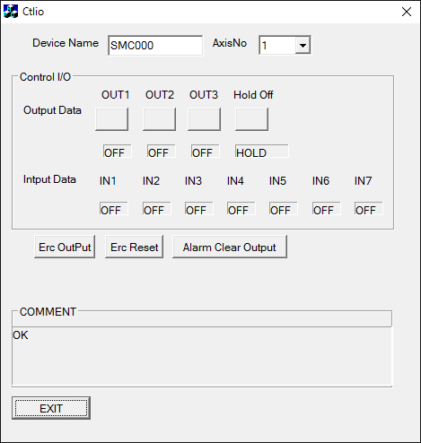
Control signal setting function
The axis that does the control I/O is selected by Device Name and axis number (AxisNo).
Control I/O
Output Data :OUT1-OUT3 is output.
Input Data :Input state of IN1-IN7 is displayed.
Erc Output
Error Counter Clear Signal is output.
Erc Reset
When a Error Counter Clear Signal is assumed to be a level setting, the signal is reset.
Alm Clear OutPut
Alarm Clear Signal is output.
The return value is displayed in the comment, and execute it again,please after confirming the content of the error and the correspondence when the setting is not effective.