The Diagnosis program is utility software that can check the operation
of digital input/output and interrupt functions.
You can also output a report on the installation status of device driver
and the diagnosis results.
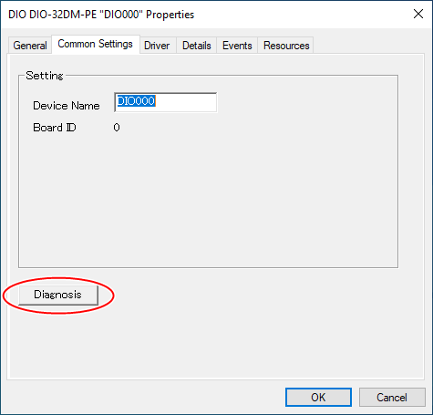
Start diagnosis program
To start the Diagnosis program, click the [Diagnosis] button on the property screen of the device manager.
Check the operation of digital input
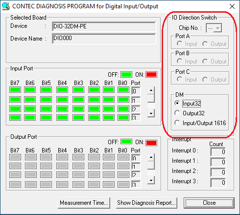
The status of the digital input is displayed in [Input Port].
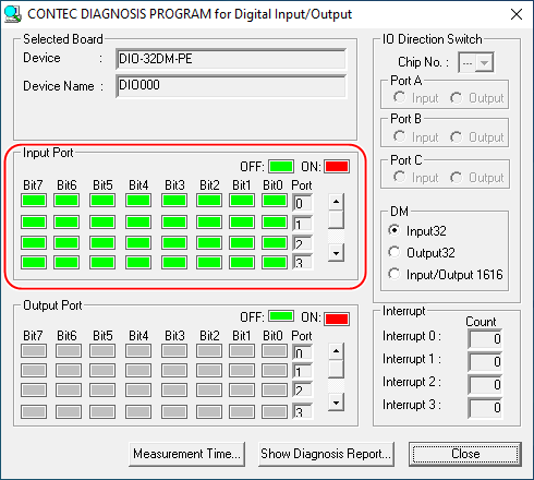
If the device has interrupt function, the number of interrupts detected for bits 0 to 3 is displayed in [Interrupt].
If the target device has no input port, [Input
Port] is grayed out.
If you are using a device that can set the input/output direction, set
the port whose operation is to be checked to [Input] in [I/O Direction
Switch].
Check the operation of digital output
The status of the digital output is displayed in [Output Port].
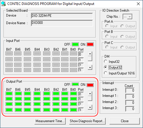
[Output port] is a switch, and the output
can be turned ON/OFF by clicking the corresponding bit.
Also, the output status of the target device is acquired and displayed
by echo back.
If the target device has no output port,
[Output Port] is grayed out.
If you are using a device that can set the input/output direction, set
the port whose operation is to be checked to [Output] in [I/O Direction
Switch].
You can switch I/O Direction for bi-directional Ditital I/O device.
There is three(3) types of bi-directional
ditital device.
Please follow the description for your device type.
There is the risk to destroy your device
if you connect the cable the wrong way.
Please refer the hardware manual of your device to connect the cable from
the terminal on the device properly after you switch I/O direction.
Device Type |
Model No. |
Description |
i8255 type |
for 48 bit: DIO-48DX-USB
for 96 bit: DIO-96D-LPE |
- There are several IC chips of i8255 mode 0 on the device. for 48 bit Digital I/O : Chip No. is from 1 to 2. - One IC chip of i8255 mode 0 has 3 ports(24bits) for Digital
I/O feature. There are 3 ports which are called Port A, Port B and Port C. - Here is the relationship's list for port vs signal terminal name on device. Port A: Terminal PA0 - PA7 - Here is the relationship's list for port vs logical port name from API function. Port A: Logical port 0 |
24DY type |
DIO-24DY-USB, etc. |
- The device has 3 ports(24bits) for Digital I/O feature. There are 3 ports which are called Port A, Port B and Port C. - Here is the relationship's list for port vs signal terminal name on device. Port A: Terminal PA0 - PA7 - Here is the relationship's list for port vs logical port name from API function. Port A: Logical port 0 - Chip No. is fixed 1 in "IO Direction Switch" item. |
32DM type |
DIO-32DM2-PE |
- The device has 4 ports (32bits) for Digital I/O feature. There are 4 ports which are called DIOA, DIOB, DIOC and DIOD. - You can choose one of DM condition in "IO Direction Switch" item. "Input32", "Output32" or "Input/Output
16/16". - Here is the relationship's list for port vs signal terminal name on device. DIOA: Terminal DIOA00 - DIOA07 - Here is the relationship's list for port vs logical port name from API function. DIOA: Logical port 0 |
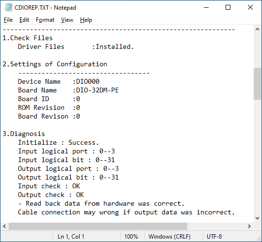
Diagnosis report
The installation status of device driver
and the diagnosis results can be output to a text file.
Click the [Show Diagnosis Report] button.
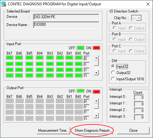
To prevent malfunction due to the execution
of diagnosis, output the diagnosis report by disconnecting the cable from
the device.
If there is an external input with the cable connected, Input check : NG
will be displayed.
After execution, the following report will be output.