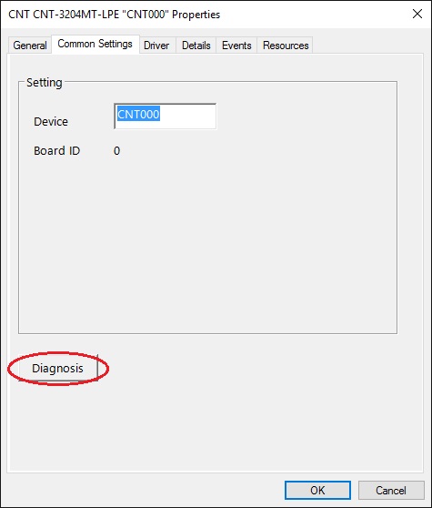
Starting the Diagnosis Program
Select the board in the property page of Device Manage, then run the Diagnosis Program.
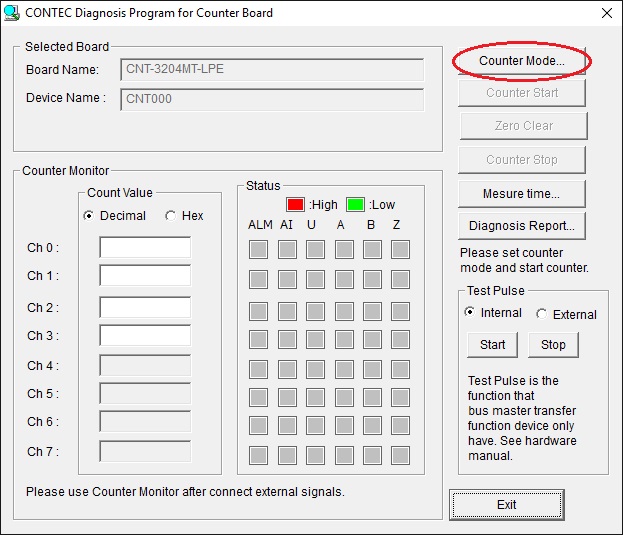
Setting counter operation conditions
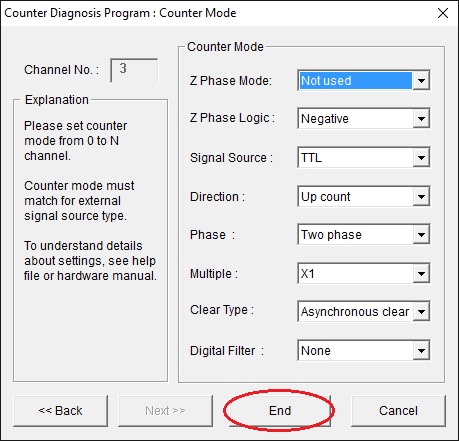
(1) Change counter mode settings. Click on [Counter Mode ].
The Counter Mode setting dialog box appears.
(2) Set the counter mode for channel 0. Please set the signal source according to the input signal. Leave the other settings at factory defaults. Click on [Use Same Mode] to make the same settings for the other channels.
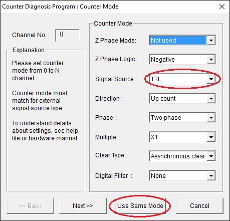
(3) Click on [End].
Checking counter operations
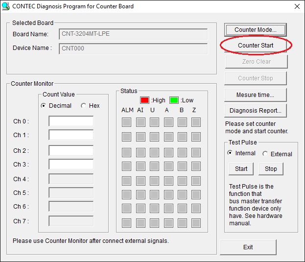
The following commands can be used to check the basic operations of the counter.
[Counter Start] : Starts the counter.
[Zero Clear] : Clears the counter to zero.
[Counter Stop] : Stops the counter.
(1) Click on [Counter Start].
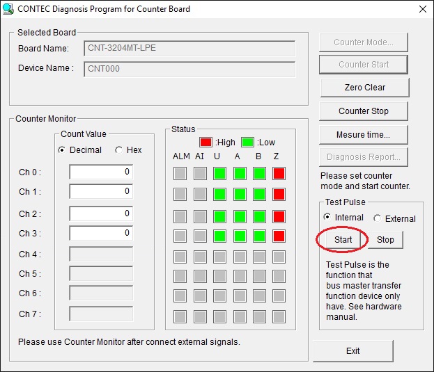
(2) The counter value of each channel is displayed along with its status (ALM, AI, U, A, B, Z).

Meaning of the status |
|
ALM |
It
indicates an occurrence status of disconnection alarm error. |
AI |
It
indicates an occurrence status of abnormal input error. |
U |
It indicates a status of general-purpose input. |
A,B,Z |
It indicates an input status of A-phase, B-phase or Z-phase. |
(3) If you use the device with sampling function, you can use the test pulse.
Click [Start] in the "Internal" setting
of "Test Pulse" to output 2-phase signals for all channels.
You can check the count value and status of all channels.
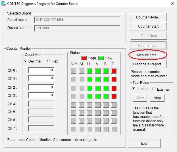
Start the Measure Execute Time Program
The Measure Execute Time program can be
started from the diagnostic program.
Click the [Measure time] button in the diagnostic program.
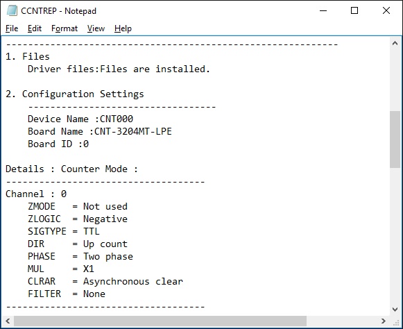
Diagnosis Report
(1) Clicking on [Diagnosis Report ] displays detailed data such as board and channel settings and the diagnosis results as saved in text format.

(2) A diagnosis report is displayed as shown below.