Overview of User Buffer
For
G-series
In the G-series, the conversion data is transferred to the user buffer
in the following format.

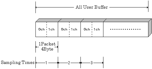
The figure above shows the transfer
method to the user buffer when Ch0, Ch1, (2 channels in total) are used.
For data transfer, a transfer packet with the size of 4 bytes is performed
in the minimum unit.
Two AD conversion data are stored as a binary value in one packet.
In the example shown above, 0 channel data is stored in the lower 2 bytes
of one packet and 1 channel data is stored in the upper 2 bytes.
When using 2 channels, 1 packet (1 transfer times) = 1 sampling.

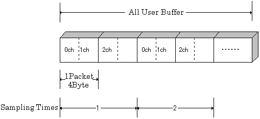
The figure above shows the transfer
method to the user buffer when Ch0, Ch1, Ch2 (3 channels in total) are
used.
Basically, one packet is used for two conversion data, as shown above,
when odd channels are used, the upper 2
bytes of the packet are unused.
When using 3 channels, 2 packets (2 transfer times) = 1 sampling.
Set User Buffer
When using the user buffer, it
is necessary to register the application memory to which the conversion
data is transferred in advance in the driver.
Use function AioSetAiTransferData
to set user buffer.
Ret = AioSetAiTransferData ( Id , DataNumber , Buffer )
In DataNumber, specify the capacity
of application memory in units of transfer packets.
A transfer packet represents the data size of the smallest unit at the
time of data transfer, and its size is 4 bytes.
In Buffer, specify the address
of the allocated array in the application.
The number of arrays must be at least as many as the DataNumber.
Example) When 1000 sampling is performed using 2 channels
Since one packet is used for one sampling, 1000 numbers of arrays are reserved and DataNumber = 1000.
Example) When 1000 sampling is performed using 3 channels
Since two packets are used for one sampling, 2000 numbers are allocated and DataNumber = 2000.
For
Z-series
For Z-series devices such as AI-1204Z-PE, the data storage method is different
from the G-series.
For data transfer, a transfer packet with the size of 4 bytes is performed
in the minimum unit.
In one packet, two A/D conversion data are stored as binary values in the
same way as G-series devices.
One piece of data is stored as follows.

One data (half data of one packet) is 16 bit
data.
Among them, the lower 12 bits are the actual data.
Among the upper 4 bit data, the data of the
lower 3 bits, which is the hatched portion in the above figure, is the
data used for calculation in the device, and is unnecessary data for the
user.
Therefore, we need to create an application to ignore this data.
The top 1 bit is a bit for judging whether
12 bit data is valid or invalid.
When this bit is 1, the data is invalid data. When this bit is 0, the data
is valid data.
Therefore, when using the user buffer, It is necessary to judge whether the top 1 bit is 0 or 1 to judge whether it is valid data or invalid data.
The data transfer method is performed in packet
units, which is same as the G-series.
For details, please refer to AioSetAiTransferData
and AioSetAiStopTimes.
Please notice that the way of storing data in packet units is different
from G-series when the number of used channels and the number of transfer
times are even number or odd number.
As follows, one packet is expressed as  .
.
When the number of used
channels is 1 (example: only Ch0 is used)

If the used channel is 1 channel and
the number of transfer times is set to even number, the data is stored
without any gap every packet, so there is no problem.
When the number of transfer times is
set to odd number, invalid data is stored in the upper 2 bytes of the
last packet.
1 is set to the top 1 bit of the lower packet.
If this bit is set, we need to make programming to ignore this data in
application.
When the number of used
channels is 2 (example: Ch0, Ch1)

When the used channel is 2 channels
The data is stored with no gap every packet, so there is no attention point in setting the number of transfer times.
When the number of used
channels is 3 (example: Ch0, Ch1, Ch2)

When the used channel is 3 channels, invalid
data is stored in the upper 2 bytes of the even data packet regardless
of the number of transfer times.
1 is set to the top 1 bit of the upper packet.
we need to make programming to ignore this data in application.
When the
number of used channels is 4 (example: Ch0, Ch1, Ch2, Ch3)

When the used channel is 4 channels, the data is stored with no gap every 2 packets, so there is no attention point in setting the number of transfer times.