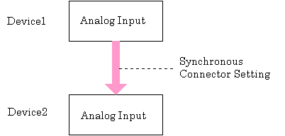
Here is an example of setting the event controller that use synchronous connector on two devices and perform analog input in synchronization.

In order to synchronize with two devices, connect the control signal of device 1 to device 2.
1. Set the start condition of analog input (Device 1)
Use function AioSetAiStartTrigger to set the start condition of analog input.
In this example software start is used.
Ret = AioSetAiStartTrigger ( Id1 , 0 )
2. Set the event controller (Device 1)
Set the event controller that connect the software start signal to the synchronous connector and output to the device 2.
The connection destination (Destination) is [Synchronous bus master signal 1].
The connection source (Source) is [Analog input software start signal].
Ret = AioSetEcuSignal ( Id , AIOECU_DEST_MASTER1 , AIOECU_SRC_START )
3. Set the clock type of analog input (Device 1)
Use Function AioSetAiClockType to set the clock type of analog input.
In this example internal clock is used.
Ret = AioSetAiClockType ( Id1 , 0 )
4. Set the event controller (Device 1)
Set the event controller that connect the internal clock to the synchronous connector and output to the device 2.
The connection destination (Destination) is [Synchronous bus master signal 2].
The connection source (Source) is [Analog input internal clock signal].
Ret = AioSetEcuSignal ( Id1 , AIOECU_DEST_MASTER2 , AIOECU_SRC_AI_CLK )
Device 2 receives the control signal from device 1 and performs analog input.
5. Set the start condition of analog input (Device 2)
Use function AioSetAiStartTrigger to set the start condition of analog input.
Since the control signal from device 1 is used as the start condition, the parameter is 10 (Event controller output).
Ret = AioSetAiStartTrigger ( Id2 , 10 )
6. Set the event controller (Device 2)
Connect the software start signal of device 1 to synchronous bus master signal 1.
Since the synchronous bus master signal 1 is connected to the synchronous bus slave signal 1 by synchronous connector, set the event controller to make the signal of the synchronous bus slave signal 1 is used as the conversion start signal of device 2.
The connection destination (Destination) is [Analog input conversion start signal].
The connection source (Source) is [Synchronous bus slave signal 1].
Ret = AioSetEcuSignal ( Id2 , AIOECU_DEST_AI_START , AIOECU_SRC_SLAVE1 )
7. Set the clock type of analog input (Device 2)
Use Function AioSetAiClockType to set the clock type of analog input.
Since the control signal from device 1 is used as the clock, the parameter is 10 (Event controller output).
Ret = AioSetAiClockType ( Id2 , 10 )
8. Set the event controller (Device 2)
Connect the internal clock signal of device 1 to synchronous bus master signal 2.
Since the synchronous bus master signal 2 is connected to the synchronous bus slave signal 2 by synchronous connector, set the event controller to make the signal of the synchronous bus slave signal 2 is used as the sampling clock signal of device 2.
The connection destination (Destination) is [Analog input sampling clock].
The connection source (Source) is [Synchronous bus slave signal 2].
Ret = AioSetEcuSignal ( Id2 , AIOECU_DEST_AI_CLK , AIOECU_SRC_SLAVE2 )
In this case, conversion starts from Device 2. When the analog input of device 1 starts, the analog input of device 2 starts synchronously with it.
9. Conversion start
Ret = AioStartAi ( Id2 )
Ret = AioStartAi ( Id1 )